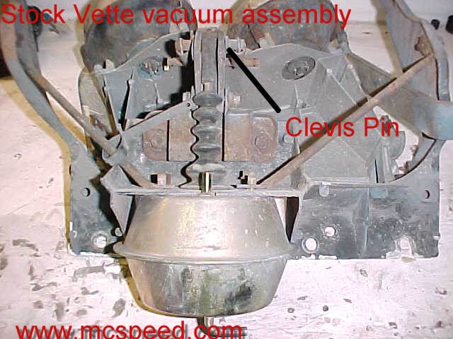
Killer Lights were inspired during the building of our '69 Killer Shark. I wanted to eliminate the stock vacuum and upgrade to a reliable late model OEM style system. I am now offering conversion kits. The kit comes with the brackets and hardware needed to install 1993-1997 Firebird headlight actuators in place of the stock vacuum system. The conversion kit is available for $99.95. You will need to obtain the actuators, module, switch, and wiring from a vendor of your choice. I have provided the installation instructions below. This should answer most FAQ. Click on the "Order Form" tab to the left to purchase a set today! There is a FAQ section at the end of this page. See the Aug 03 VETTE magazine article here: VETTE ARTICLE. |
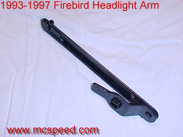
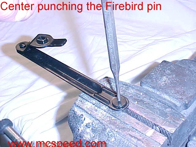
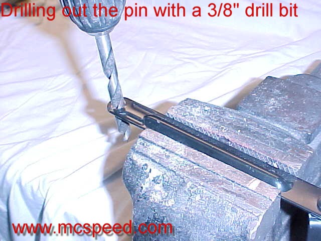
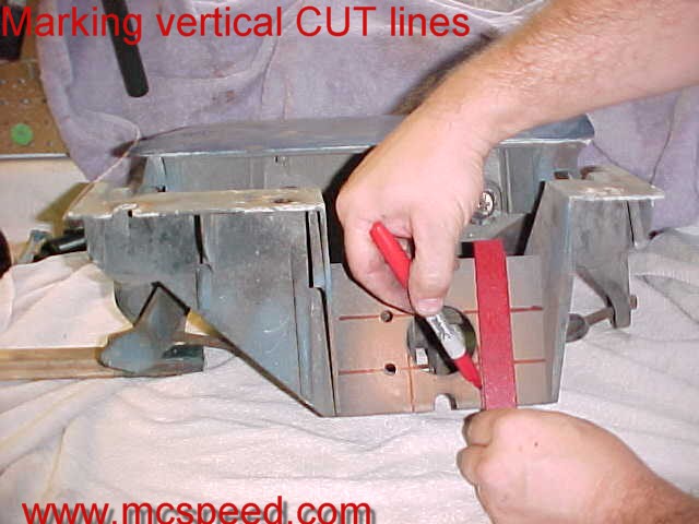
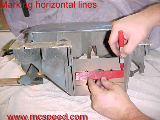
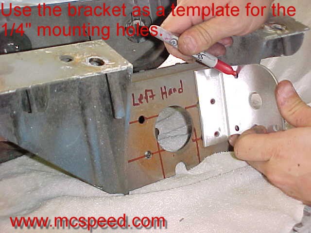
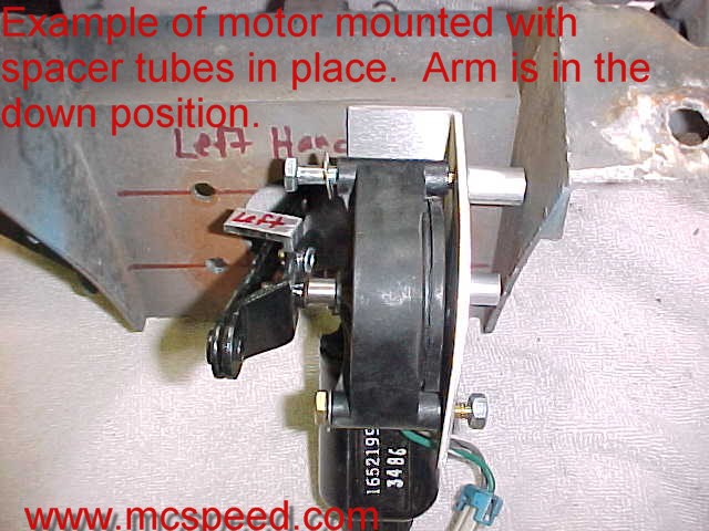
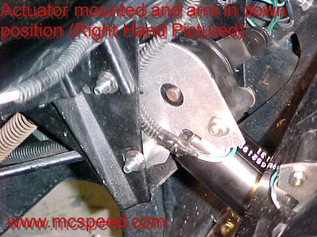
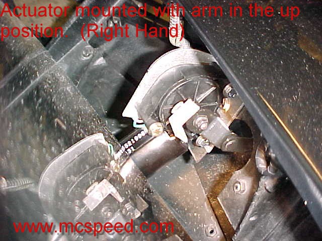
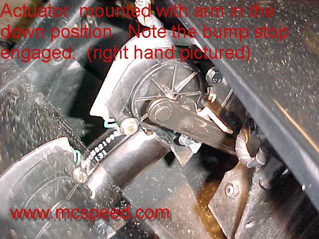
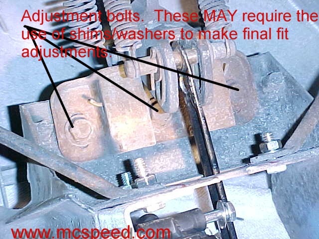
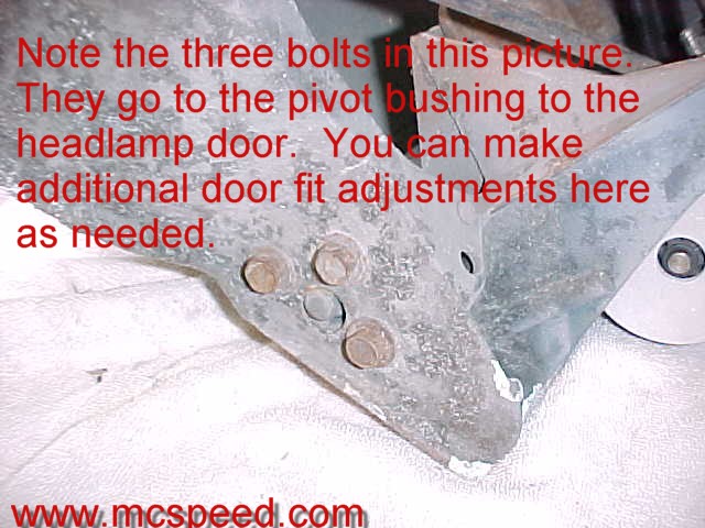
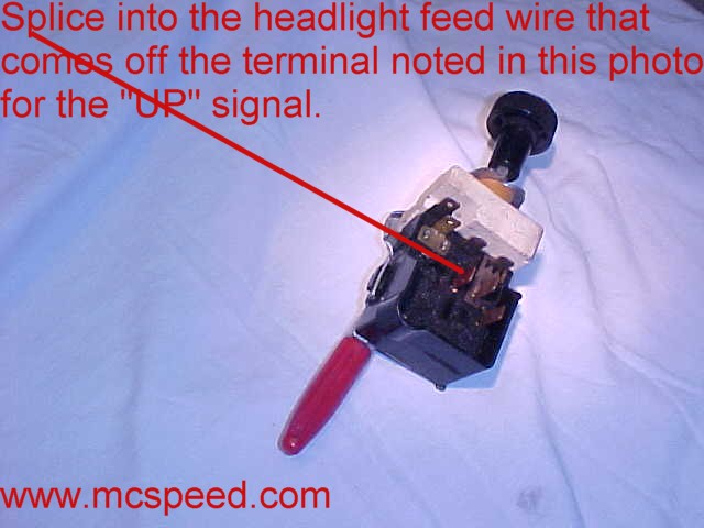
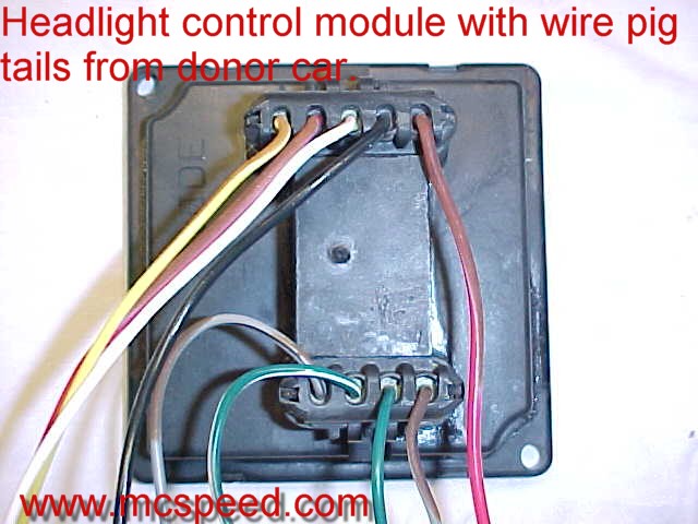
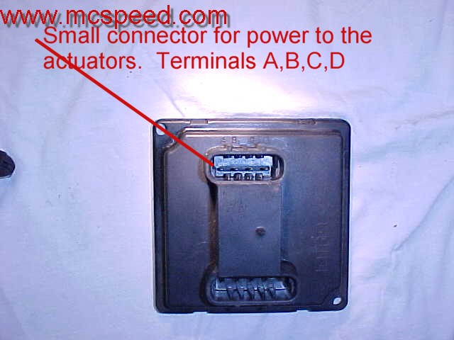
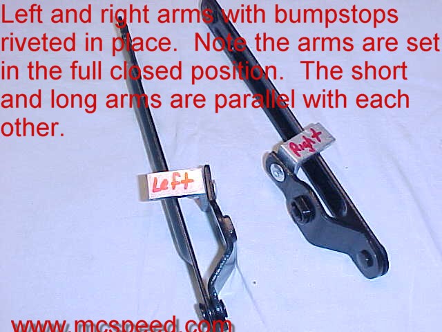
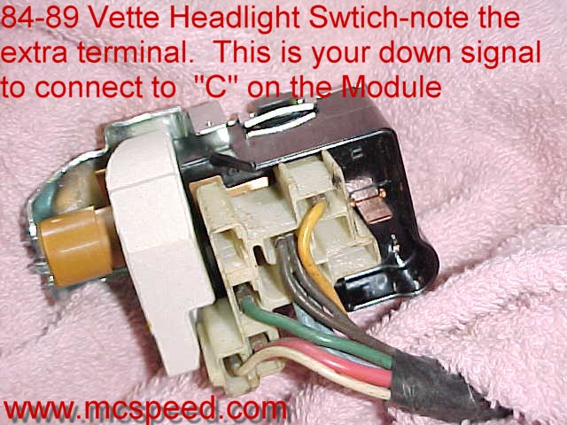
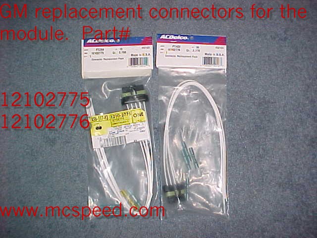
Parts Needed: Click on the part numbers for a hot link to www.gmpartsdirect.com for great GM parts deals. GM Parts direct now offers all the electronic parts in one kit! Click HERE 1. Killer Light brackets and hardware kit 2. 1993-1997 Firebird Headlight actuators and lift arms-click HERE for a great deal on new ones. (note-if purchased new, they come with the lift arms. If you purchase yours from a salvage yard, make sure they include arms.) GM part # for new actuators Left 16516653 Right 16516654 3. Headlight Control Module- 1990-1996 Vette GM part #16521297 4. 1984-1989 Corvette headlight switch GM part # 1995257 (not needed if using the Firebird Control Module) 5. Bulk wire for running the connections (14-16 gauge) 6. 1993-1997 Firebird replacement weather pack pig tails for the control module connection, or small female solderless terminals (radio shack). If you are obtaining your parts from a salvage yard, clip the wire harness and purchase the weather pack termnals to the module and headlight actuators. Use of the OEM weather pack terminals will yield a much more professional final product. However, solderless connectors sealed with silicone (RTV) will work fine. GM part number for connectors: New GM replacement Connector # Large- 12102775 Small- 12102776 Tools Needed: 1. Drill bits- 3/16", 1/4", 3/8" 2. Center punch 3. Bench vice 4. Drill motor (90 degree tip needed if installing on the car-or dremel with drill bit tip) 5. Reciprocating saw (or hand saw with hack saw blade-metal grade cutting) 6. Sharpie, or other marking device 7. Rivet gun 8. 7/16" wrench/socket 9. Pliers 10. 1/2" wrench/socket and extension 11. 10mm wrench/socket Mounting Insructions: Installation can be done on the car!!!!!!!!!!!!!!! (click on the thumbnails for a full size picture) 1. First remove the stock headlight vacuum assembly. Retain the clevis pin 2. Prepare the Firebird arms. First, center punch the Firebird pivot pin, and drill it out with a 3/8" bit. Position the arms in the down position. Set the bumpstop in place as seen in the photos. Drill the bumpstop and arm with a 3/16" bit. Rivet the bump stop in place using the 3/16" rivet provided. Refer to the photos below to indicate the bumpstop mount in relation to left and right hand arms. 3. Use a straight edge and scribe a horizontal line running exact center of the stock vacuum actuator mounting holes. Take the same straight edge and scribe a verticle line down each side of the large round hole where the stock vacuum actuator arm travels. Use your reciprocating saw to cut down on the verticle lines. This will allow room for the new arm to travel. This can be done in the car. I suggest removing the hood, however, it is not necessary to do so. Next, place the Killer light bracket against the assembly you are working on. Line up the front mount holes with the horizontal lines you scribed. Slide the bracket against the side of the headlight support assembly that is closest to the center of the car. Mark the side mounting holes (two) using the bracket as a template. Drill these holes out with a 1/4" bit. If doing this in the car, use a 90 degree drill tip, or a dremel for easy access. Use the left bracket on the left assembly, right bracket on the right assembly. 4. Mount the bracket on the headlight assembly with the 1/4"x20x3/4" bolts. Put a washer on each side of the bolts. Leave these bolts loose (just start the threads. Using the actuator in the same orientation as it came off the Firebird (left hand/right hand) Insert the 1/4"x20x2" bolt in the free standing portion of the bracket (finger tight). Insert the two 1/4"x20x3" bolts through the actuator on the arm side through the bracket. Slip a spacer tube between the bracket and stock headlight assembly. You may need to grind it down shorter, or add a washer. Some headlights are cast different. Finally, push the 3" bolt thorugh the stock assembly, install a washer and nut. Keep everything finger light. When all the bolts are in place, you may tighten them starting with the 3/4" long bolts. Slip the correct (left hand/right hand) arm into place. 5. Insert the stock clevis pin with the Firebird arm in place of the stock clevis mount. Re-attach the stock springs . At this time you may need to manually operate the actuator up and down to align with the position of the door. Tighten the 10mm arm to axle bolt on the actuator. The following photos include pictures of the assembly in the car with the arms in the up or down position. Notice how the bumpstop locks the arms into the shortes possible length in the down position. 6. Now you want to run the actuator all the way up and down. Note the position of the headlight door. The next step is to adjust the closed position of the door. You may loose 2-5% of you full open position after final closed adjustments. That will be correct when you re-aim the headlamps. In order to adjust the close position so that the door fits flush with the body of the car, you will need to loosen the three mounting bolts for the pivot armature shown in the picture below. They require a 1/2" socket with an extension. You can reach from below and slide the armature forward and back to affect the final resting point when closed. You may also add washers between the armature and headlight assembly to get additional adjustment. You can also adjust by shimming the main mounting points of the entire headlight assembly to the car, the pivot bushing mounts on each side of the assembly, and the single armature adjustment screw seen in the pictures below. 7. Remove the stock headlight switch from the dash according to standard removal procedures. Install the 84-89 Corvette switch. Re-install your original C3 shaft and nob. The following wiring connections correlate to the larger of the two plugs on the control module. Run two 14-16 gauge wires from wherever you plan to mount the module to the headlight switch. You will note the 84-89 switch has an extra terminal that will be open when you plug the stock C3 harness back in place. This is the DOWN feed terminal. Attach a female spade to that terminal. This wire goes to terminal "C" on the module. Splice into the main headlight "on" feed at the switch. I have noted that in the photo below. This is the wire that only gets power when the headlights come on. It is usually blue, but can vary from year to year. This wire feeds the high/low beam switch. Attach the other end of this wire to the "A" terminal on the control module. Run a 15 amp fuse (one fuse in each wire) in two separate 14-16 gauge wires from a battery (all the time powered) post to terminal "B" and "E" on the module. You can pick up power off the battery post on the starter, then route the two wires to the module in the most neat and clean way possible. These wires provide the power to the actuators. Run a solid chassis ground to terminal "D" on the module. The module should be mounted in an area out of direct weather, with sufficient access to probe the harness as needed for trouble shooting. It is best to mount it on the fender well in front of the left front tire. The following wiring connections correlate to the small plug on the module. These wires go from the module to the actuators. Terminal "A and B" apply to the left actuator. Terminal "D and E" apply to the right actuator. Each actuator has two wires. If you have snipped a harness from the junkyard, simply reconnect with bulk 14-16 gauge wire between the module and motor. If you are making solderless connections, run the terminals from the module to the actuators. Connect the wires at the actuators (you will have to cut the factory weather pack plug off if hard wiring your light system). No matter where you left the lights (open or closed), they will cycle to the right spot when you pull the switch. If they go backward from each other, or from the switch, reverse the wires at each actuators. Do not mix up any wires from A and B with wires from D and E. 8. Follow standard wiring procedures for soldering, crimping, and taping all wire surfaces. Aim your headlight beams, and secure any loose wires. ***NOTE*** You will be amazed at the number of people that FREAK out when they see these on your car . Please use common sense when "showing off" your killer lights. I have been asked to raise and lower them more than a dozen times an hour while showing my car. This constant raising and lowering will reduce the overall life of the motors. Watch to make sure nobody has their hands anywhere near the lights when showing them off, as serious injury could result in closing a headlamp door on a finger or hand. ***This conversion will not prevent you from returning to VACUUM at a later date. The metal removed below the stock clevis rod hole is not visible once the stock vacuum actuator is reinstalled. ***All stock pivots, bushings, and springs must be in good working order for a succesful conversion! Additional Information: The weak link on the 4th Gen Firebird actuators is the plastic main gear. There is a solution to this problem. This may also help you to use a set of USED actuators that have been discarded due to a gear failure. I have contaced the following vendors. They carry replacement metal gears. *For a stock replacement metal gear that reuses the rubber inserts, see: *For solid metal replacement gears, see: FAQ Can I reinstall the vacuum at a later date? A. Yes. The only mod to the stock assembly is the small cut and two 1/4" holes. Can I do the install on the car? A. Yes. You must remove the front grilles, and jack the car up enough to gain access from the bottom. I have performed the conversion with the hood on, but I would suggest you at least move it for additional access. Q. Can I buy everything from you (actuators, motors, switch, and brackets)? A. In some circumstances (overseas customers, etc) I am willing to build a complete kit. However, I recommend you purchase your electronics. This way you can get them replaced if needed in the event you have a defective part. I highly recommend the use of salvage parts to keep the cost of the conversion to a minimum. Q. How much can I expect to spend to complete the kit? A. Per www.gmpartsdirect.com as of 11/05. C4 switch and module: Switch #1995257 $20.09 Connector 1 #12102775 $22.03 Connector 2 #12102776 $22.03 C4 Module #16521297 $97.47 Actuator Left 16516653 Right 16516654 $149.09 X2 C4 Module and switch conversion = $459.80 + $99.95 for the kit = $559.75 Firebird module (no switch replacement needed) Connector 1 #12102775 $22.03 Connector 2 #12102776 $22.03 Actuator Left 16516653 Right 16516654 $149.09 X2 Firebird Module #16525685 $132.44 Firebird Module Conversion = $494.77 + $99.95 for the kit = $594.72 Q. How long will it take to install a set of Killer Lights? A. The install should take the average do-it-yourselfer the better part of a day. Q. On a scale of 1-10 (10 being the hardest), what is the Killer Light conversion? A. This all depends on your skills and abilities, comfort level with wiring, and tools on hand. For a skilled mechanic, this is a 3. For the once in a while Weekend Warrior, it is a 7. Q. What other things should I consider when performing this conversion? A. You must make sure that all your stock pivots, bushings, aiming adjusters, and hardware are in good condition. You want to verify you have a good solid chassis ground to the frame. Your battery must have a full charge to operate the lights properly--this also applies to testing of the system. Q. What if I get into a bind....where can I turn for help? I will make every effort possible to answer your questions via email. Simply use the form listed on the Order Form page with your inquiry. You must provide a return email address for me to reply. Q. What is the difference between the C4 switch/module conversion and Firebird module conversion? A. The C4 switch and module conversion allows you to park the headlights in the UP position without the beam glowing. The Firebird conversion raises the light pod as soon as the light is on and will drop the light pod when the light is off with no park mode for washing the headlight pod, etc WITHOUT the beam glowing. That is the ONLY difference! *Disclaimer* Purchaser/Installer assumes all liability for injury to self, others, or property damage as a result of the installation or use of the electric headlight conversion. There are no warranties or guarantees provided with this product. |
Killer Lights-Because Vacuum SUCKS!!!! |


McSpeed |
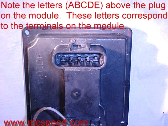
Large Connector: A=UP B=12 volt in C=Down D=Chassis Grount E=12 volt in Small Connector: A/B= left side actuator power D/C= right side actuator power |
***Wiring Update**** If using the 93-02 Firebird module (Part # 16525685) the wiring is a bit different. The up signal is wired exactly the same and can be done using the stock C3 headlight switch. The down signal is accomplished by simply grounding terminal "C" on the Firebird control module. This will cause the lights to drop as soon as they are turned off, even if the parking lights remain on. The upside to this option is you don't have to replace the headlight switch, and if you have a floor mounted highbeam (early C3) switch, you can splice into the "up" headlight on wire there and avoid pulled the dash panel apart to access the switch. Please send me a note if you have any questions about using the 1993-2002 Firebird headlight control module. You can purchase the Firebird module kit from GM Parts Direct by clicking HERE. |
***Note*** Several installers have been able to complete the conversion without making the verticle cuts on the stock housing. You might want to test fit and adjust your lights before making the verticle cut. In the least, you may need only to dremel a small amount of material for clearance on the lift arms. Cutting the material out will assure full clearance for the lift arm operation. |